
Finned Tube Manufacturing
Drawing-based fin forming and welding support for heat exchanger tube projects.
DLSS supports integral low-fin and high-frequency welded finned tube requirements, from material and drawing review through processing, inspection and protective packing.
The manufacturing route is reviewed against the tube and fin materials, finished geometry, wall or attachment requirements, and project inspection specification.

Two Manufacturing Routes, Different Controls
The fin construction determines how the tube is processed and which finished-product requirements must be verified.
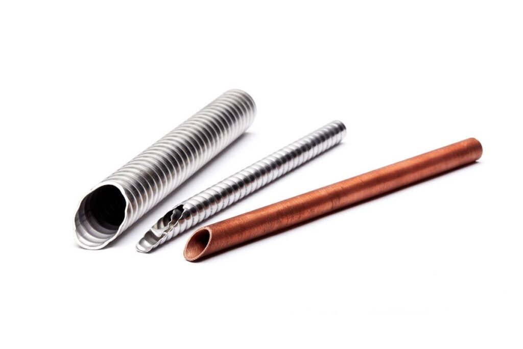
Integral Low-Fin Forming
Integral fins are produced by cold forming the parent tube material rather than attaching a separate fin strip.
Manufacturing review focuses on the finished fin profile, wall thickness beneath the fins, plain sections and required material condition.
Key Controls
Fin Profile · Root Diameter · Finished Wall · Plain Sections
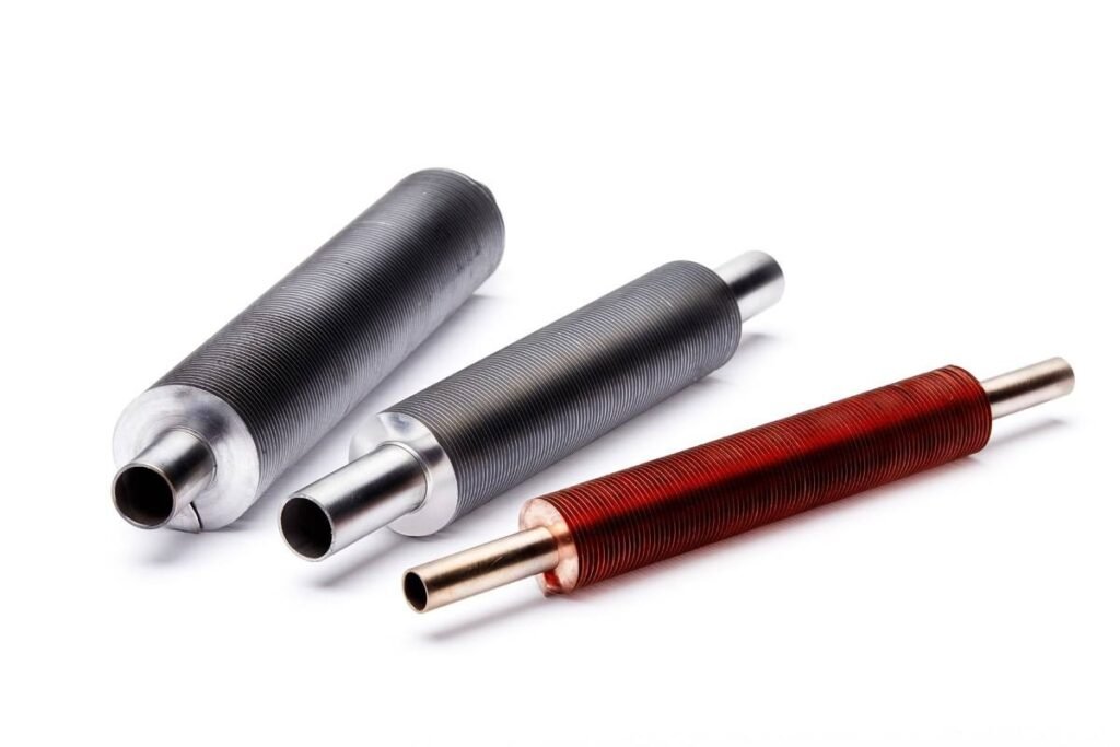
High-Frequency Fin Welding
A separate fin strip is wound helically around the base tube and continuously joined by high-frequency resistance welding.
Manufacturing review addresses the tube and fin-strip materials, fin geometry, welding procedure and specified attachment acceptance requirements.
Key Controls
Tube & Fin Materials · Pitch · Welding Process · Attachment Quality
Integral fin forming and fin-strip welding require different process controls and acceptance criteria. They should not be treated as the same manufacturing route. Other fin constructions can be submitted for a separate technical review.
Drawing & Process Controls
The drawing and purchase specification should define the finished tube—not only the starting material.
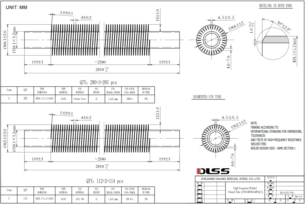
Material & Product Specification
Base Tube · Fin Material · Governing Requirements Confirm the tube grade, construction and applicable specification. For welded fins, identify the fin-strip material separately.
Fin Geometry
Fin OD · Height · Thickness · Pitch Define the fin profile and measurement units. Include root diameter where applicable.
Finned & Plain Sections
Overall Length · Finned Length · Plain Sections Confirm the length and position of finned sections, plain ends and intermediate unfinned areas.
Wall Beneath Integral Fins
Finished Minimum Wall · Verification Method Agree on the minimum remaining wall and how compliance will be checked after forming.
Welded Fin Attachment
Procedure · Acceptance Criteria · Inspection Define applicable welding requirements, qualification records where required, and attachment acceptance criteria before production.
Finished Material Condition
Heat Treatment · Temper · Surface Confirm the required condition after processing, including any specified heat treatment or cleaning.
Applicable Product Requirements
Integral-finned tube requirements may involve ASTM A1012, ASTM A498 or ASTM B359, depending on material, dimensions and scope. Welded fin-strip construction requires its own applicable project, welding and inspection requirements.
Trial production, first-piece approval and inspection hold points are agreed where required by the project.
Finished-Tube Inspection & Records
Inspection methods, measurement locations, frequency and acceptance criteria are agreed against the finished-product specification and project inspection plan.
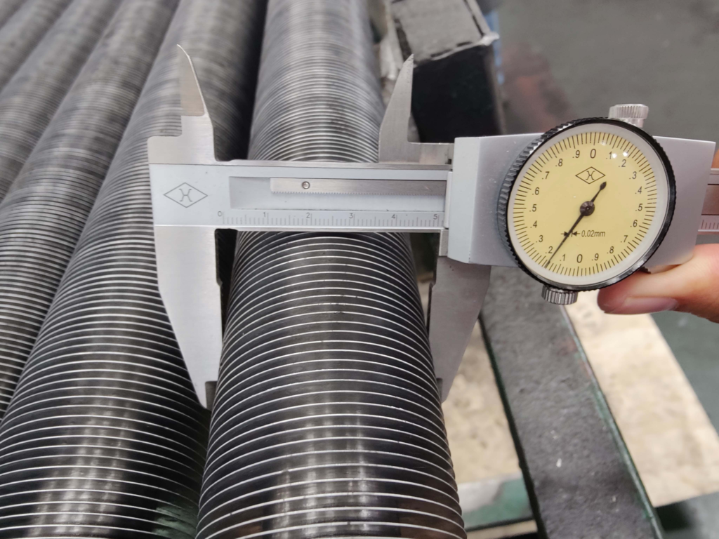
Material Identification
Tube · Fin Material · Traceability
Fin Dimensions
Profile · Height · Thickness · Pitch
Tube Length & Layout
Overall Length · Finned Sections · Plain Ends
Wall or Attachment Verification
Integral-Fin Wall · Welded-Fin Attachment
Surface & Fin Condition
Tube Surface · Fin Condition · Cleanliness
NDE & Pressure Testing
Applicable Methods · Agreed Coverage
Supporting Documentation
Material Records · Fin Dimensional Report · Applicable Wall or Attachment Records · Required Test Reports · Heat Treatment Records Where Required · Traceability
Base-tube testing does not automatically replace required inspection after finning.
Fin Protection & Traceability
Packing is reviewed against the tube length, fin geometry, bundle weight and handling requirements.
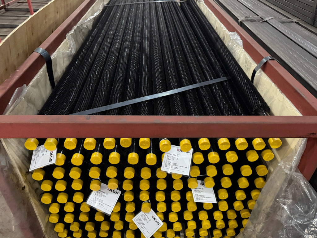
Fin & Surface Protection
Suitable Supports · Contact Protection · Tube Separation
Tube-End & Bundle Restraint
Protected Ends · Controlled Movement · Handling Arrangements
Identification & Packing Records
Material References · Tube Identification · Packing List
Special lifting, stacking and receiving requirements should be identified before the packing arrangement is confirmed.
Related Products & Technical Guides
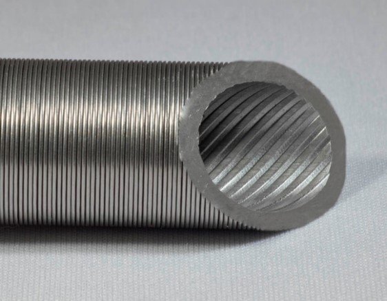
Finned Heat Exchanger Tubes
Explore fin constructions, material options and finished-tube purchasing requirements.
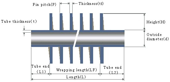
Fin Root Diameter
Understand the relationship between fin outside diameter, root diameter and the finished tube profile.
Residual Wall After Finning
Review finished-wall requirements and the information needed for inspection acceptance.
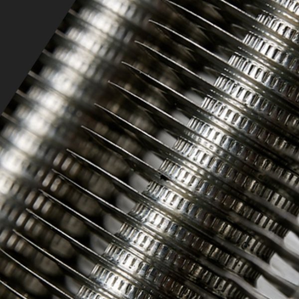
Finned Tube Standards
Find product requirements by material family and fin construction.