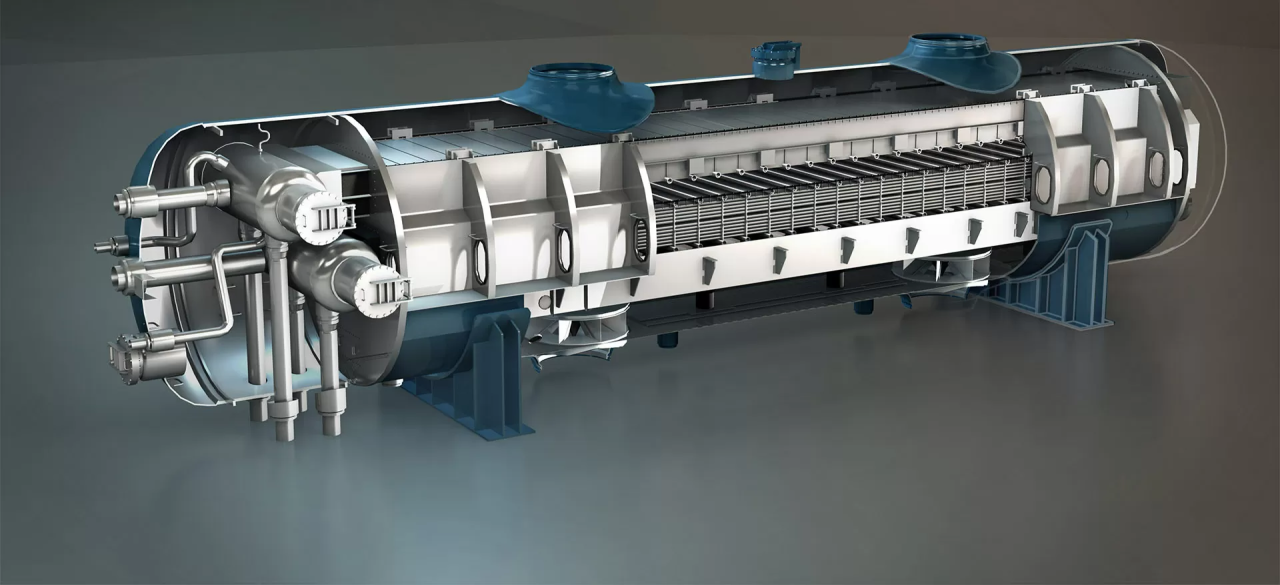
1. Introduction – Shell and Tube Heat Exchanger Design
A shell and tube heat exchanger is one of the most widely used heat exchanger types in industrial applications due to its versatility, durability, and ability to handle high pressures and temperatures.
When planning a new installation or upgrading existing equipment, it is essential to consider several key design factors that directly influence efficiency, reliability, and maintenance requirements.
For related topics, see 5 Proven Ways to Improve Heat Exchanger Efficiency, 7 Effective Ways to Prevent Fouling in Heat Exchangers, Best Material for Seawater Heat Exchanger, and Heat Exchanger Maintenance Checklist.
2. Tube Bundle Design
- Tube Diameter & Thickness: Select dimensions based on fluid type, flow velocity, and pressure requirements.
- Tube Layout: Common patterns include triangular and square pitch; triangular maximizes heat transfer surface area, while square facilitates cleaning.
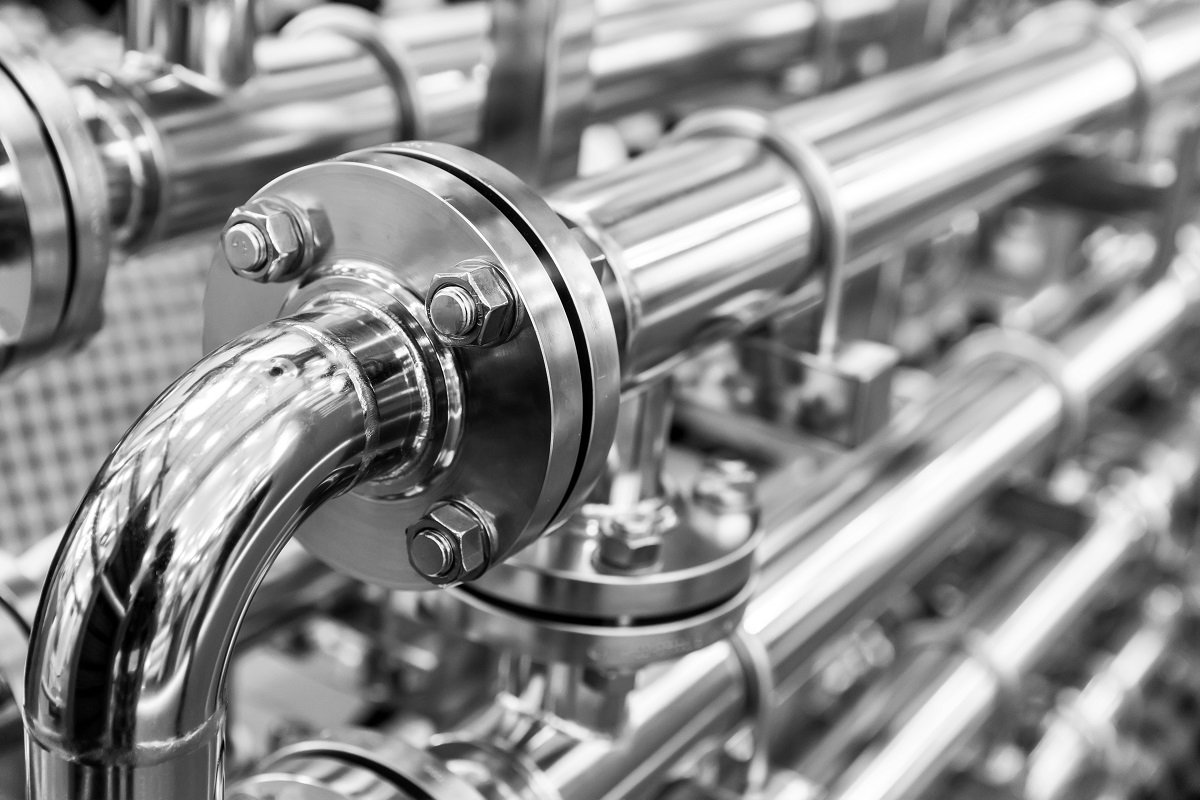
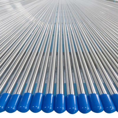
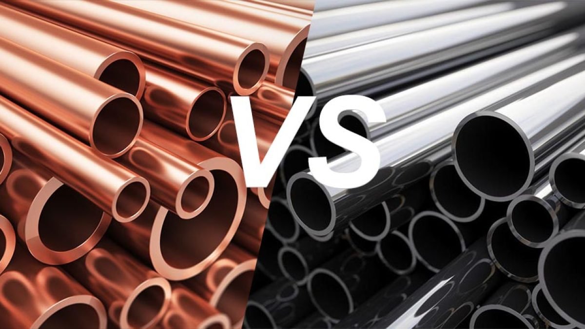
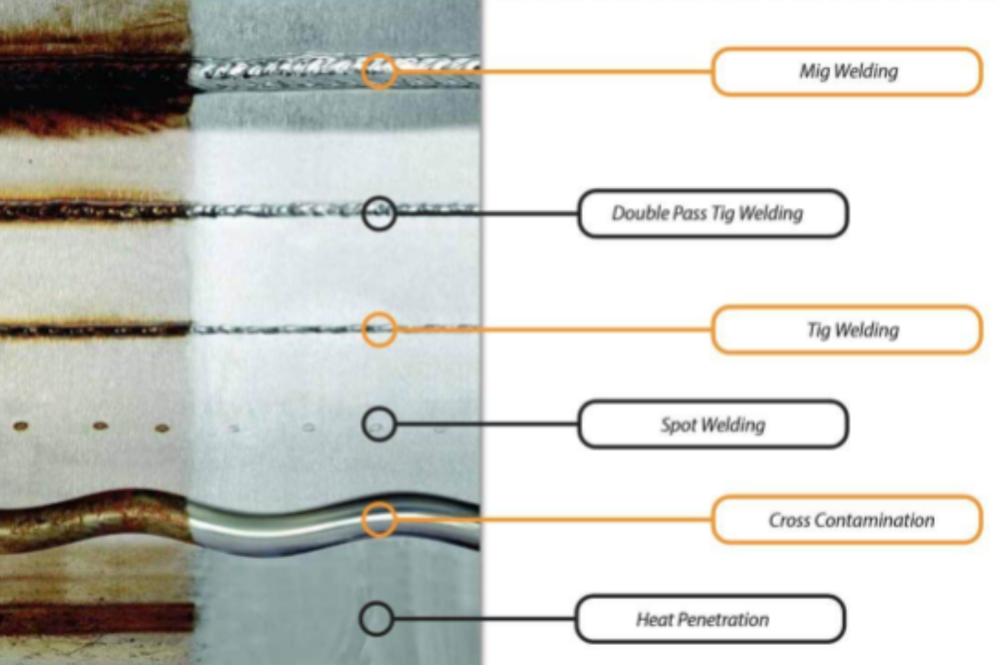
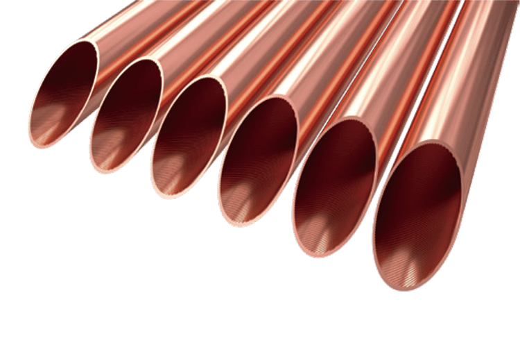
- Tube Material: Choose corrosion-resistant alloys like 316L, duplex 2205, or titanium for seawater or chemical service. See our heat exchanger tubes for more details.
3. Shell-Side Configuration
- Shell Diameter: Must accommodate the tube bundle with sufficient clearance for thermal expansion.
- Baffle Design: Baffles guide shell-side flow to improve turbulence and heat transfer while supporting the tubes.
- Baffle Spacing: Tighter spacing improves heat transfer but increases pressure drop; find the right balance based on process requirements.
4. Flow Arrangement
- Single Pass vs. Multi-Pass: Multi-pass arrangements allow greater heat recovery and smaller units for the same duty, but may increase pressure drop.
- Counterflow vs. Parallel Flow: Counterflow maximizes the temperature driving force, improving efficiency.
- Not sure which type fits your duty? Compare options in plate vs shell and tube heat exchangers. When your duty is set, confirm key steps for sizing a shell and tube heat exchanger.
5. Fouling Considerations
Design should minimize areas of low velocity where deposits can settle. For long-term performance, see 7 Effective Ways to Prevent Fouling in Heat Exchangers.
6. Mechanical Design and Standards
- Design Codes: Ensure compliance with ASME Boiler and Pressure Vessel Code or TEMA standards for pressure-containing equipment.
- Thermal Expansion: Include expansion joints or floating heads to handle temperature differences between shell and tubes.
7. Maintenance Access
- Removable Tube Bundle: Simplifies inspection and cleaning, particularly for seawater-cooled units.
- Manways and Nozzles: Properly sized for internal access and ease of maintenance.
8. Real-World Example
A petrochemical facility redesigned its seawater-cooled shell and tube exchanger using duplex stainless steel tubes, optimized baffle spacing, and a counterflow arrangement. This reduced fouling rates by 35% and improved thermal efficiency by 12%, extending maintenance intervals from 9 months to 15 months.
9. Conclusion
Effective shell and tube heat exchanger design balances thermal performance, pressure drop, fouling resistance, and maintenance requirements. By choosing the right tube material, optimizing baffle and flow design, and adhering to industry standards, you can achieve high efficiency and long service life.
For more on maintenance, read Heat Exchanger Maintenance Checklist, and for corrosion-resistant material selection, see Best Material for Seawater Heat Exchanger.
Contact DLSS
At DLSS, we manufacture high-quality stainless steel tubes for heat exchanger applications, ensuring optimal heat transfer, corrosion resistance, and long service life.
Email: info@dlsspipe.com
Website: www.dlsspipeline.com
Related Reading