1. Introduction – Shell and Tube Heat Exchanger Sizing
Proper shell and tube heat exchanger sizing ensures optimal performance, energy efficiency, and long service life. Incorrect sizing can lead to excessive pressure drops, fouling, or insufficient heat transfer.
This guide outlines the key design parameters to consider when sizing a shell and tube heat exchanger, whether for new installations or retrofits.
For related topics, see Shell and Tube Heat Exchanger Design Considerations, 5 Proven Ways to Improve Heat Exchanger Efficiency, and Heat Exchanger Troubleshooting Guide.
2. Determine Thermal Duty
Thermal duty (Q) is the total heat load the exchanger must handle, calculated as:
Q=m×Cp×ΔT
Where:
- m = mass flow rate
- Cₚ = specific heat of the fluid
- ΔT = temperature change required
Accurate thermal duty ensures the exchanger has enough surface area to meet process requirements.
3. Select Flow Arrangement
- Counterflow: Maximizes temperature difference, improving efficiency.
- Parallel Flow: Simpler design but lower heat recovery.
- Multi-Pass: Allows greater heat transfer in compact units but may increase pressure drop.
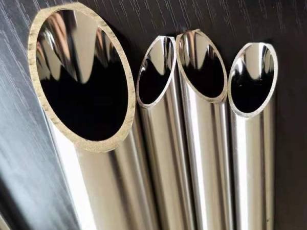
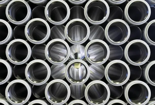
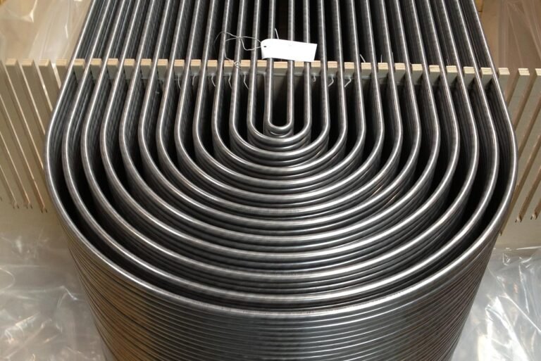
4. Tube Count and Length
The number and length of tubes directly impact heat transfer surface area.
- More tubes increase capacity but also cost and size.
- Tube length typically ranges from 1m to 6m for industrial applications.
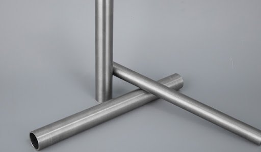
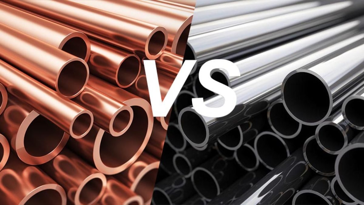
Material choice is equally important—see Heat Exchanger Tube Materials. - Before finalizing geometry, revisit STHE design considerations, and verify tube alloy suitability in this materials overview.
5. Tube Diameter and Pitch
- Tube Diameter: Common sizes range from 12.7 mm (½”) to 25.4 mm (1″).
- Tube Pitch: Triangular pitch maximizes surface area; square pitch facilitates cleaning.
6. Shell Diameter
Shell size must accommodate the tube bundle plus clearance for thermal expansion. The relationship between shell diameter and tube layout is defined in TEMA standards.
7. Baffle Design
- Baffle Spacing: Closer spacing increases heat transfer but raises pressure drop.
- Baffle Cut: Typically 20–40% of shell diameter to balance turbulence and flow distribution.
8. Pressure Drop Considerations
Excessive pressure drop reduces system efficiency and increases pump power requirements. Aim for the lowest pressure drop that still maintains adequate turbulence for heat transfer.
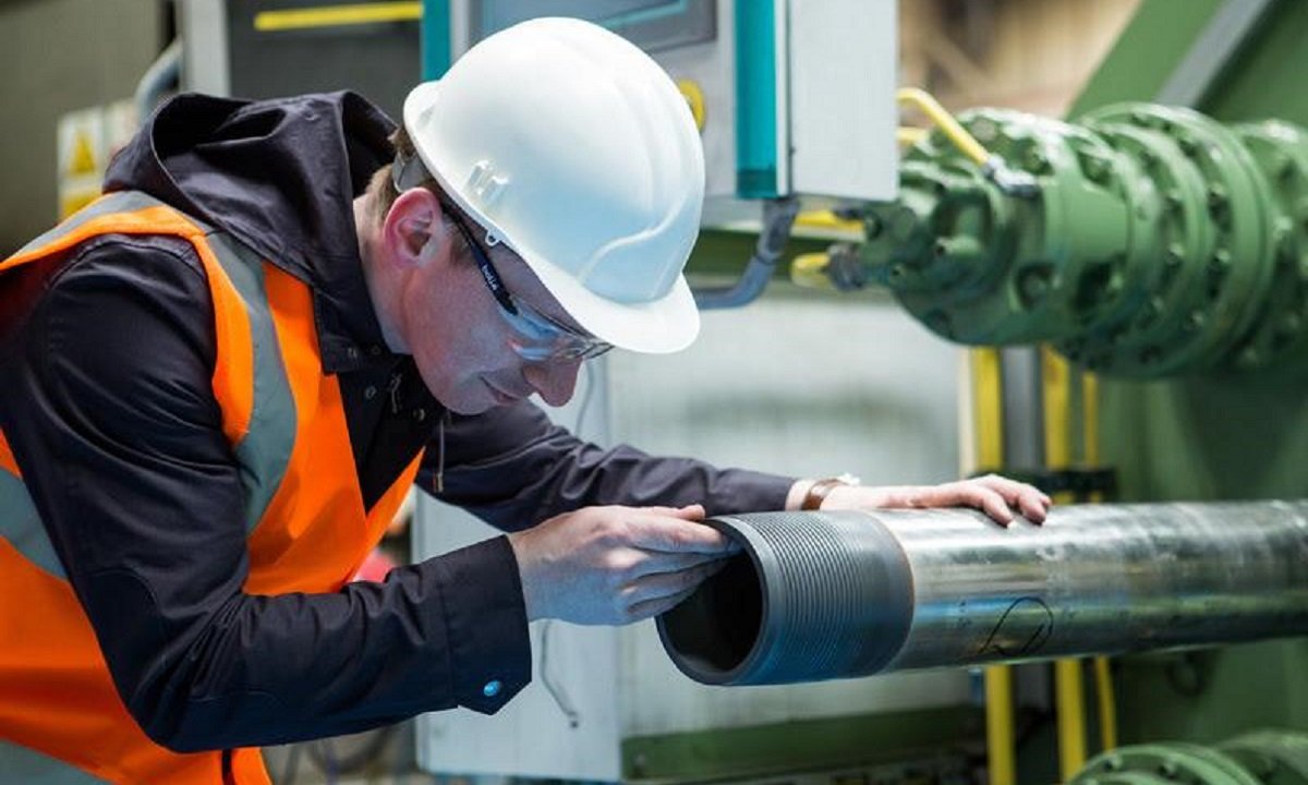
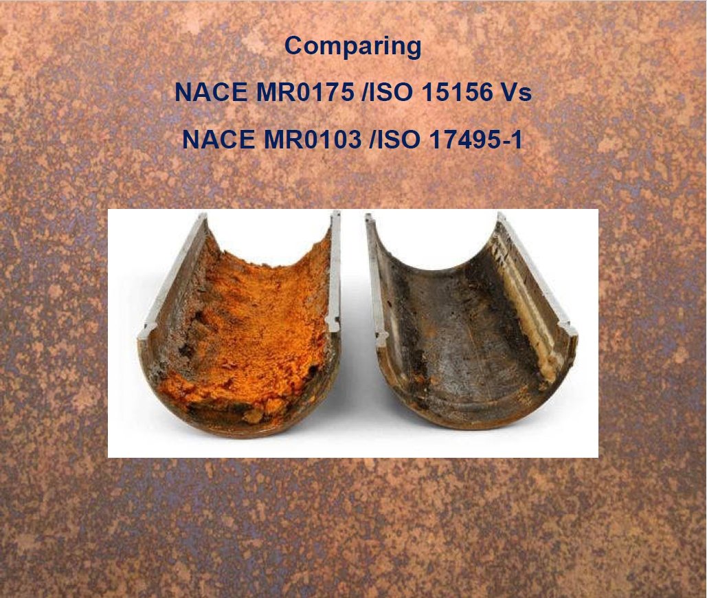
9. Fouling Factors
Include fouling resistance in calculations to ensure long-term performance. For prevention tips, see 7 Effective Ways to Prevent Fouling in Heat Exchangers.
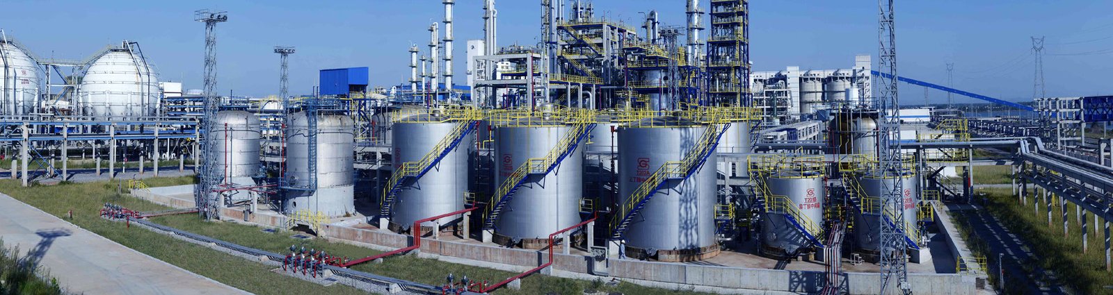
10. Real-World Example
An oil refinery resized its seawater-cooled shell and tube exchanger using duplex stainless steel tubes, optimized baffle spacing, and a counterflow arrangement. The redesign improved heat recovery by 15% and extended cleaning intervals by 40%.
11. Conclusion
Correctly sizing a shell and tube heat exchanger requires balancing thermal performance, pressure drop, fouling resistance, and mechanical constraints. A well-sized unit can deliver years of efficient and reliable service.
For guidance on material selection and long-term maintenance, read Best Material for Seawater Heat Exchanger and Heat Exchanger Maintenance Checklist.
Contact DLSS
At DLSS, we manufacture high-quality stainless steel tubes for heat exchanger applications, ensuring optimal heat transfer, corrosion resistance, and long service life.
Email: info@dlsspipe.com
Website: www.dlsspipeline.com
Related Reading