
U-Bending for Heat Exchanger Tubes
Drawing-based tube bending with specified geometry, post-bend requirements and inspection arrangements.
DLSS supports U-bending projects from drawing review and tube preparation through forming, specified post-bend treatment, inspection and protective packing.
Bending feasibility and acceptance requirements are confirmed against the material, tube dimensions, bend radius and project specification.

Drawing & Dimensional Review
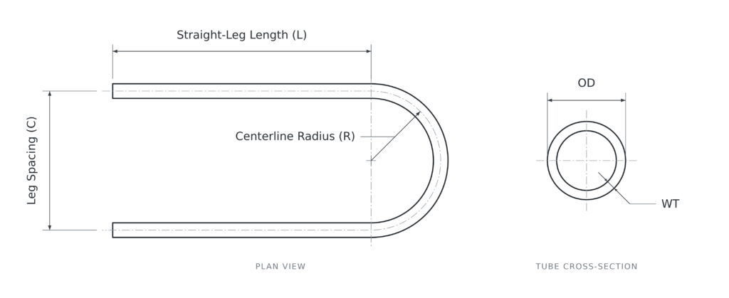
The bending drawing should define the required geometry, dimensional references, tolerances and acceptance limits.
Tube Material & Dimensions
Grade · Construction · OD · WT · Wall Basis Confirm the base-tube requirements before reviewing the bend.
Centerline Bend Radius
Specified Radius & Tolerance Identify the centerline radius clearly on the drawing.
Straight-Leg Length
Finished Length & Measurement Reference Define where the leg length is measured and any required end projection.
Developed Length
Cutting Length & Trimming Allowance Review the tube length required for forming and final end preparation.
Bend-Wall & Ovality Limits
Remaining Wall · Thinning Limit · Ovality Definition Agree on the acceptance limits and how each requirement will be assessed.
Leg Spacing & Alignment
Leg Spacing · Parallelism · Bend Plane Define the finished geometry required for bundle assembly.
Dimensional references and tolerance definitions must be confirmed before bending. Overall length, straight-leg length and developed length should not be used interchangeably.
From Base Tube to Finished U-Bend
Base Tube Preparation
Review material identification, tube condition, dimensions and required cutting lengths before forming.
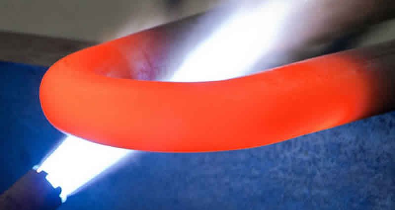
Tooling & Forming
Review the tooling and forming approach for the required tube size and radius. Trial bends or first-piece approval are arranged where specified.
Post-Bend Condition
Confirm any required heat treatment, surface treatment or cleaning according to the material and project specification.
Final Preparation
Complete agreed trimming, end preparation and identification before final inspection and packing.
Post-Bend Heat Treatment
Post-bend heat treatment is determined by the material, degree of forming, service conditions and governing specification. Where treatment is required, the method, treated area, temperature control, cooling requirements and records are agreed before processing.
Applicable Requirements
The project requirements combine the base-tube specification, any applicable U-tube standard, the exchanger drawing and agreed processing requirements.
Bend Inspection & Records
Inspection methods, measurement locations, frequency and acceptance criteria are agreed against the finished-tube requirements.
Bend Geometry
Radius · Leg Length · Leg Spacing
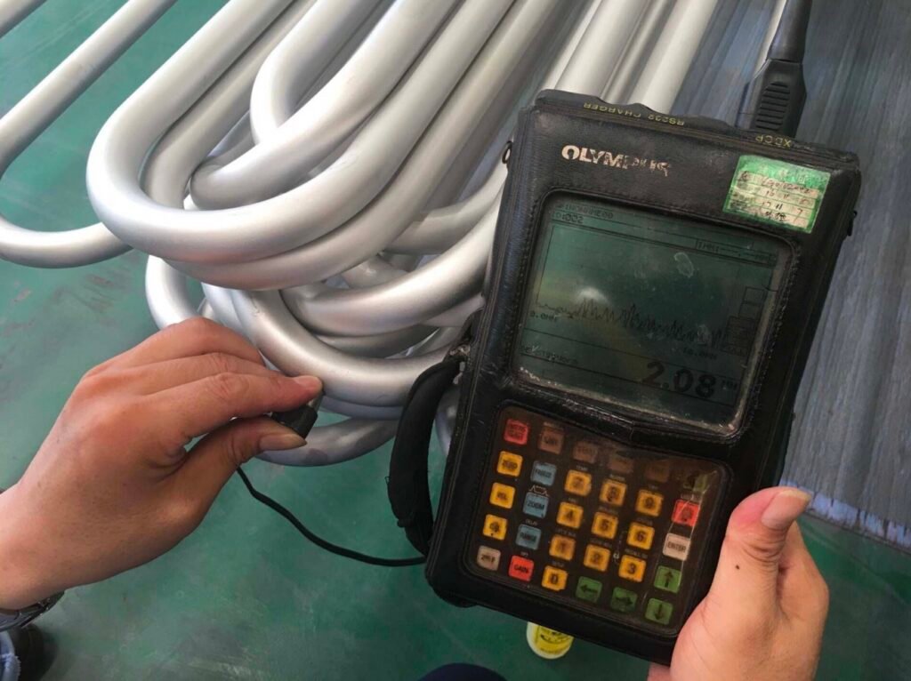
Wall Verification
Bend-Area Wall Thickness & Specified Limits
Ovality & Alignment
Roundness · Parallelism · Bend Plane
Surface & Cleanliness
Bend Surface · Tube Ends · Internal Cleanliness
NDE & Pressure Testing
Applicable Methods & Agreed Coverage
Third-Party Inspection
Witness Points · Records · Inspection Release
Supporting Documentation
Base Tube MTC · Bend Dimensional Report · Required Wall & Ovality Records · Test Reports · Heat Treatment Records Where Required · Traceability
Certificate type and third-party validation arrangements are confirmed before production.
Test suitability and coverage are confirmed for the finished geometry. Any inspection limitations or untested areas must be identified and addressed in the agreed inspection plan.
U-Bend Protection & Packing
Packing is reviewed around the finished bend geometry, leg length, material and shipment requirements.
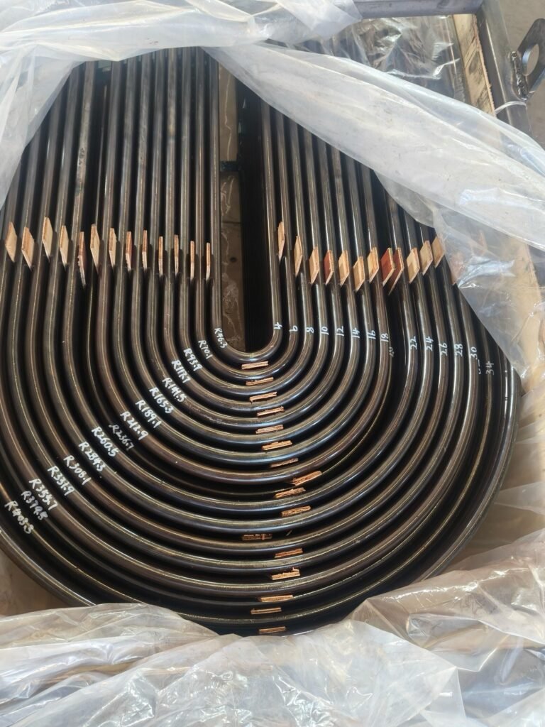
Bend-Area Support
Protected Curves · Suitable Supports
Leg & End Protection
Supported Legs · Protected Tube Ends
Identification & Grouping
Radius Groups · Tube Identification · Packing Records
Test suitability and coverage are confirmed for the finished geometry. Any inspection limitations or untested areas must be identified and addressed in the agreed inspection plan.
Related Products & Technical Guides
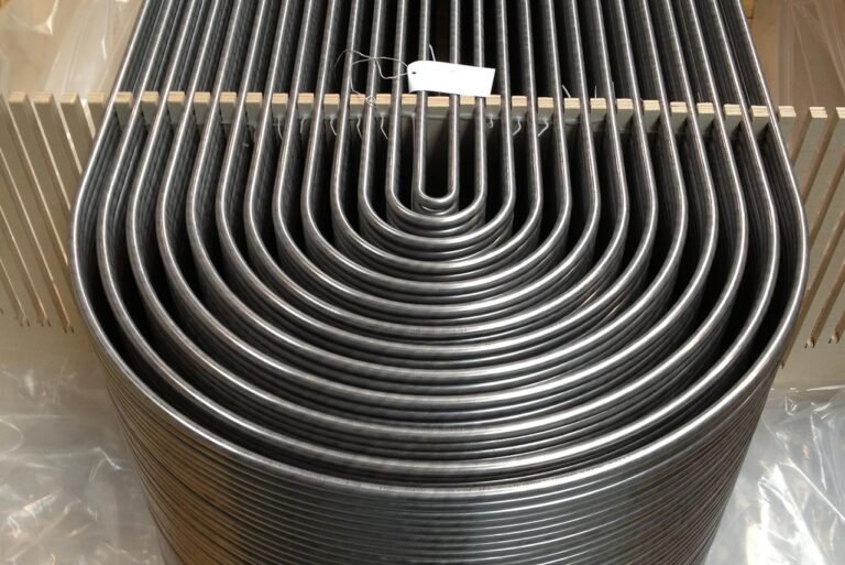
U-Bend Heat Exchanger Tubes
Explore tube materials, product specifications and U-tube purchasing requirements.
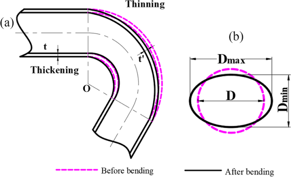
U-Bend Wall Thinning
Review bend-wall requirements and the information needed for acceptance.
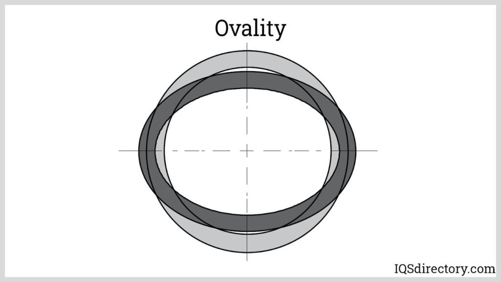
U-Bend Ovality
Understand roundness requirements, measurement definitions and acceptance limits.
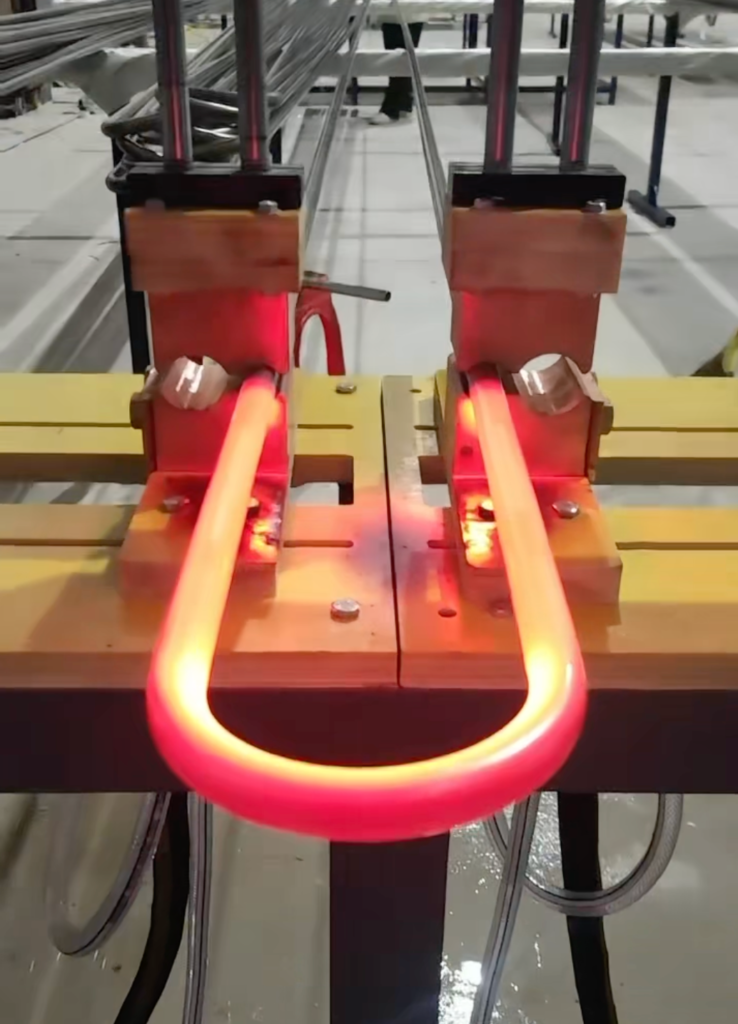
Heat Treatment & Solution Annealing
Review material-specific treatment and documentation arrangements.